The USSC90, the index-registers.
 Programmers manual.
The index-registers.
The three index-registers were meant to enhance the programming of loops.
Clear appointments had to be respected to the indexregisters,
else different program-parts would interfere, using the same index register.
A card-reading routine needed two indexregisters, one as a band-pointer for buffer-tranfers and one as memory-pointer.
For the main-program there remained one indexregister.
Our USSC was equipped with three index registers: IR1, IR2 and IR3. These indexregisters were optional.
For indexing operand-addresses the programmer had to write :
- 04 bit set in the instruction-code = to make use of IR1,
- a negative sign before the instruction = to make use of IR2,
- both, negative sign and 04 = to make use of IR3.
On execution the content of an index-register was added to the operand address.
When in such addition a carry occurred from a 100 addition, it was ignored: 0187+0015=0002.
This caused that indexed operands were always addressed within the same band.
All instructions with an operand-address or a band-number in M could be indexed.
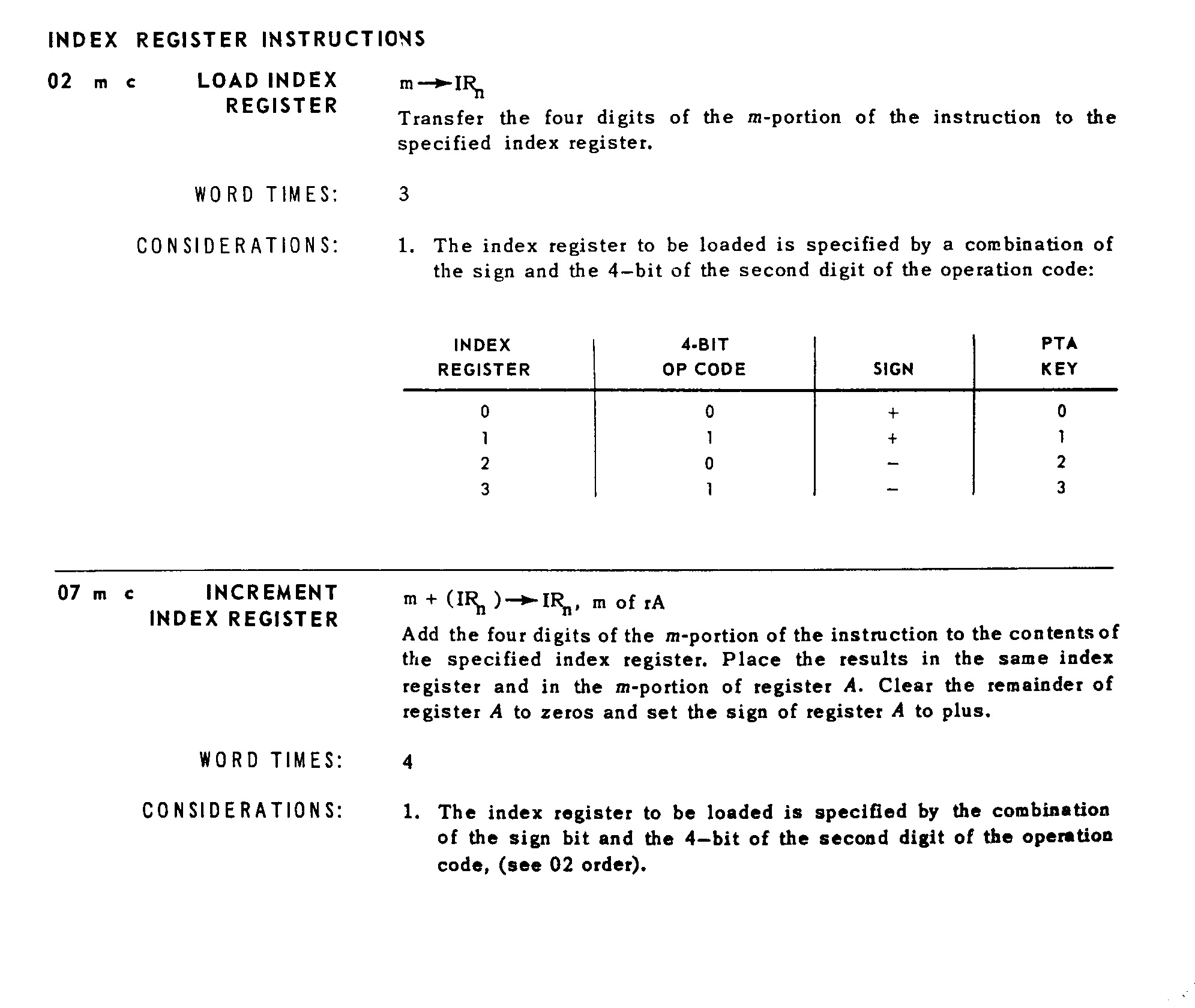
Instruction 02 loaded an index register with (M).
To load an indexregister with 500, one had to program:
+0Y 0500 1123 to load 500 into IR1,
- 02 0500 1123 to load 500 into IR2,
- 0Y 0500 1123 to load 500 into IR3.
( Y stands for the bit-pattern (2 AND 4) and 1123 was the address of the next instruction.)
Instruction 07 incremented the content of an index register with (M).
To add 12 to an index-register one had to program:
+0y 0012 0590 to add 12 to (IR1), ( y stands for (7 AND 4) ).
- 07 0012 0590 to add 12 to (IR2),
- 0y 0012 0590 to add 12 to (IR3). Instruction 07 also placed the sum in M of rA for end-of-loop comparisons.
To decrement the value in an indexregister an addition with the numbers complement of 10000 or 200 was made.
+0y 9997 0590 subtract three from the indexregister IR1
+0y 0197 0590 did the same.
Menu:
.Home
.CPU
.Software
.Instructions
.Calculations
.Punchcards